Thursday 27 March 2014

FLASH MAGIC TUTORIAL

Here we learn that, how to burn the program in a microcontroller.

We use Flash magic software for this purpose.

Note :-
             Flash magic only works on those microcontrollers which have serial ports or support serial programming. It can not burn the microcontrollers like at89c51 or others which does not support serial programming.

STEPS :-
         
1. Open the flash magic.


2.  select your microcontroller.
                                      

3.  select your baud rate. (usually it 7200 or 9600).


4.  select your com port.


5. To see your com port follow below steps. Right click on the my computer and click onmanage.
                                

6.  Then click on device drivers. Now click on Usb com ports and see your com port. If you use usb to serial cable (RS232) then it is shown as usb portliftic cable.


7.  Now check the box ERASE ALL FLASH.
                                       

8.  Check the box VERIFY AFTER PROGRAMMING.
                                     

9.  Click on brows to brows your program Hex file.


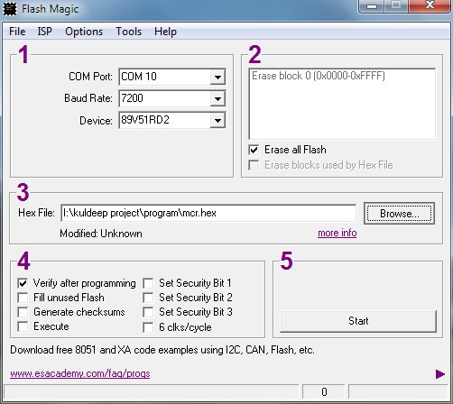
10.  Now Click START to start the burning process.

Errors :- 

1. If there is error of changing the baud rate then change your baud rate and try again.

2. If there is error of connection and then check your com port again.


IF YOU HAVE ANY QUERY THAN CONTACT US .

8051 PROGRAMMER KIT

Here we design a 8051 programmer kit for P89V51RD2 controller. With this kit you can burn the programs into micro controller.

Description of component needed are described below :

RS232 Cable :-
                            We use USB to SERIAL RS232 cable for sending the data to the microcontroller from computer. (for communication drivers of rs232 cable must be installed on your computer).


DB9 serial port :-
                                 We mount female port on the transmitter because cable contains male port.


MAX232 IC (Voltage Shifter) :-
                                                      MAX232 IC is used to shift the voltage level of computer's input to level of microcontroller. Means input from serial cable first given to the MAX232 and then given to the controller.
Connection of serial port with MAX232 is shown in figure.


Circuit Diagram :-

Components Required :-

7805 IC - 1
12v battery - 1
1N4007 diode - 1
1000uf capacitior - 1
LED - 2
330 ohm resistance - 2
10uf capacitor - 2
0.1 uf capacitor - 4
33pf capacitor - 2
11.0592 crystal oscillator - 1
P89V51RD2 controller - 1
max232 IC - 1
female serial port - 1
RS232 usb to serial cable - 1
push button - 1
10k ohm resistance - 1
connecting wires
PCB


How to burn :-

We can burn this controller with FLASH MAGIC software.


IF YOU HAVE ANY QUERY THAN CONTACT US.
  

  GOOD LUCK


Monday 24 March 2014

Flashing LED Circuit

A Circuit that flashes an LED on and off. 

Overview 

This circuit uses the 555 timer in an Astable operating mode which generates a continuous output via Pin 3 in the form of a square wave. This turns the LED (D1) on and off. The speed at which the LED (D1) is turned on and off is set by the values of R1 and R2. 

Schematic 

Flashing LED CircuitParts List 

1x - NE555 Bipolar Timer
1x - LED (Red)
1x - 470K Resistor (1/4W)
2x - 1K Resistor (1/4W)
1x - 1�F Electrolytic Capacitor (16V)
1x - 9V Voltage Battery