Pulse-width
modulation (PIC16F877A)
In this tutorial we are
using PIC 16F877A for demonstrating PWM generation using CCP module. PIC
16F877A contains two CCP modules.
Pulse Width Modulation, or PWM, is a technique for
getting analog results with digital means. Digital control is used to create a
square wave, a signal switched between on and off.
In creating pulse with
various widths for PWM two factors are important.
1.
Period of the pulse.
2.
Its Duty Cycle.
DC = Duty Cycle is pulse that stays high relative to entire
period.
It is stated in the
form of percentages(%).
For example = Pulse with a 4ms,2ms period that stays HIGH
for 1ms has DC of 25%.
(1ms/4ms=25%)
(1ms/2ms=50%)….
PERIOD
OF PWM
Frequency of PWM
is a fraction of the Fosc, the crystal frequency.
PIC16F877A microcontroller is used here PWM control.
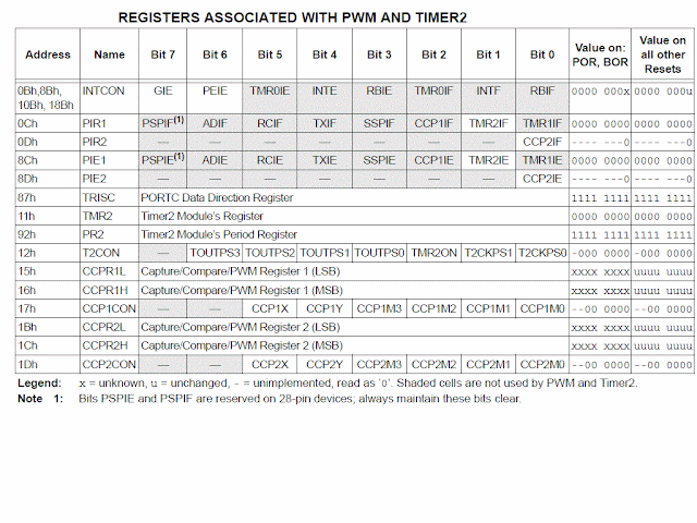
Use PR2 register to set the PWM period .
Tpwm=[(PR2)
+1]4xNxTosc.
Tosc=1/Fosc,the crystal frequency.
Tpwm=Desired PWM period.
N=Prescaler.
SETUP
FOR PWM OPERATION
The following steps should be taken
when configuring
the CCP module for PWM operation:
1. Set the PWM period by writing to
the PR2 register.
2. Set the PWM duty cycle by writing
to the
CCPR1L register and CCP1CON<5:4>
bits.
3. Make the CCP1 pin an output by
clearing the
TRISC<2> bit.
4. Set the TMR2 prescale value and
enable Timer2
by writing to T2CON.
5. Configure the CCP1 module for PWM operation.
Note
2 : All PWM modules in
a PIC Microcontroller uses Timer 2 for its operation, so you cannot set
different frequencies for different PWM modules.
In Pulse Width Modulation mode, the CCPx pin produces up
to a 10-bit resolution PWM output. The
PWM duty cycle is specified by writing to the CCPR1L register and
to the CCP1CON<5:4> bits. Up to 10-bit resolution is available. The
CCPR1L contains the eight MSbs and the CCP1CON<5:4> contains the two
LSbs. This 10-bit value is represented by CCPR1L:CCP1CON<5:4>.
CODE
#include<pic.h>
#include<htc.h>
#define _PIC16F877A_H _CONFIG(WDTE_OFF
& FOSC_HS & PWRTE_OFF & LVP_OFF & BOREN_OFF);
void main()
{
PR2=0xFF; // setting minmum frequency i.e 255.
CCPR1L=80; // 8 upper bit resolution or PWM duty
cycle
TRISC2=0; //setting CCP1 as output
CCP1CON=0x3C; //2 lower bit resolution
T2CON=0x01; // setting prescaler.
TMR2ON=1; //timer2 on
{
while(!TMR2IF) ; //checking timer2 flag
overflow
TMR2IF=0; //reset
the timer 2 flag to 0
}
}
NOTE: By changing the the value of CCPR1L you
can change the PWM duty cycle.
PROTEUS DIAGRAM
WAVEFORM
For more information contact me at chandershh@gmail.com.


No comments:
Post a Comment